

Concepts and What's New
Concepts
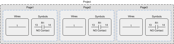
Users create a new project by opening the New Electra Drawing template. Visio drawings can contain multiple pages and each page can contain one or more wires and symbols. Symbols represent real world components and always has a reference name (R1), pin names (13 & 14) and description (NO Contact). Double click or right click on a symbol for more operations, including setting pin names and editing references.
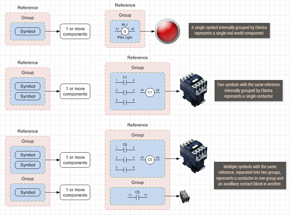
In Electra, all symbols with the same reference are initially organized into a single group, where they can be assigned to one or more components. Users can then divide the same symbols into further groupings, and each group can then to be assigned to one or more components.
Component information are stored in the drawing file for portability. Files that are shared or sent, retain all their data inside the drawing. Users manage component information in a drawing by clicking on menu Electra | Manage Components. The component database stores all component specifications for easy access, without the need to type and re-type specifications. Users select components from the database to be used on the drawing and can add, edit or delete additional components into the database.
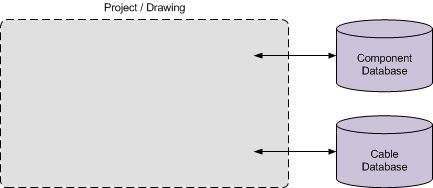
Wires represents real world cables and always has a wire name. Wires can use wire links to extend to another location or to another page. Each wire can be assigned to a cable, or to a specific core of a multicore cable. Numerous wires on a drawing can be assigned to a multicore cable. Cable information are stored in the drawing file for portability and can be easily shared or sent without losing their data. Users manage cable information in a drawing by clicking on menu Electra | Manage Cables. The cable database stores all cable specifications for easy access, without the need to type and re-type specifications. Users select cables from the database to be used on the drawing and can add, edit or delete additional cables into the database.
What's New in Electra E8
- Added new terminal layout shape.
- Able to generate terminal layout one by one.
- Able to generate jumpers when generating terminal listing.
- Added PLC parts - Sinking/Sourcing, AC, DC.
- Added page revision title block data.
- Able to sync title in title block and page name.
- Able to generate Tubing Reference report.
- Able to generate Hosing Reference report.
- Able to generate Tubing BOM report.
- Able to generate Hosing BOM report.
- Able to generate Pneumatic Connections report.
- Able to generate Hydraulic Connections report.
- Remind users if no pin name is set during create new symbol.
- Able to hide terminal block reference when renumbering terminal list.
- Able to sort symbols in Stencil Browser.
- Added Component Tag symbol.
- Able to assign cable to multiple wires.
- Added spring return key switch symbol.
- Able to hide default cable in reports.
- Able to set orientation for multiple shapes.
- Able to hide pin name for multiple shapes.
- Improved the connection point text generation in Set PLC Module window.
- Added spacing between cables in Cable Reference report.
- Changed pin name format in reports.
- Added loading message when sorting wire links.
- Simplified Document Options.
- Added Option to disable autorename for wires and symbols in Ladder Zone.
- Able to update multiple Ladder Zones number at once.
- Added Wire Bus symbol.