Panel Layout
The Panel Layout Process
To generate panel layout, follow the process as listed below:
- Complete schematic drawings.
- Create a new page and set scale and measurement units.
- Place base plates, cable ducts and rails on the new page.
- Click on menu Electra | Generate Layout and use the Generate Layout window to assign components.
- Click on Generate or Generate All button to generate layout.
- Use guides to place and align layout shapes.
Preparing a Page for Panel Layout
Pages on the New Electra drawing template are set at 1:1 scale and measurement units set at inches. These page settings are optimized for schematic drawings. To prepare a page for panel layout drawings:
- Right click on a page tab and select insert page.
- On the Page Setup dialog, select the Page Properties tab.
- On the measurement units drop down, select millimeters.
- On the Page Setup dialog, select the Drawing Scale tab.
- Click on the custom scale radio button.
- Type in your custom scale (Recommended: 1:5 for smaller panels and 1:10 for bigger panels).
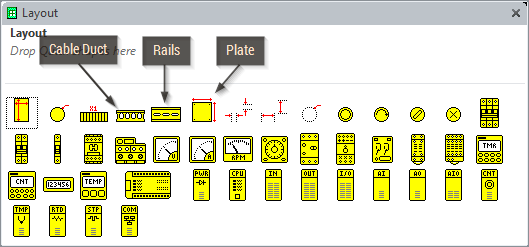
Inserting Plates, Cable Ducts And Rails
One of the first thing to do during panel layout drawings is to insert a plate (base plate or front plate). To insert a plate, select the Layout stencil and drag the plate symbol to your drawing. All Plate symbols have automatic dimensions that you can show or hide by right clicking on the plate. Users can also set units for plates, cable ducts and rails to be displayed on a drawing by right clicking on these symbols.
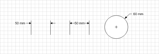
Dimension Shapes
To measure length and diameters, Electra provides dimensioning shapes on the Layout stencil to be dragged and dropped on drawings. All of them automatically display the dimension when their handles are dragged. Right click on dimension shapes for more options.
Generating Panel Layout
To generate panel layout:
- Click menu Electra | Generate Layout.
- Ensure that all references are matched correctly with components.
- Click the Generate All button on the Generate Layout window.
- Place and arrange generated components on your panel layout drawings.
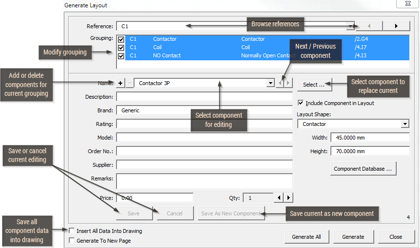
When the Generate All button is pressed, Electra will automatically synchronize your panel layout to your schematics. For example, you may have added or deleted some symbols on your schematics, and Generate Layout will insert or delete components accordingly. If you have changed the references of your schematics, GenerateLayout will also automatically reflect this change.
Using Guides to Place Layout Shapes
To create a guide:
- Drag on the ruler in Visio and drop a guide in any position.
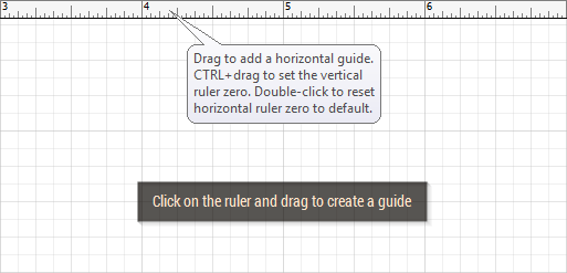
Once a guide is created, drag layout symbol to guides for attachment (shape handles will turn red). When guides are moved, all syymbols that are attached to guides will automatically move and follow guides.
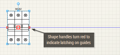
Placing shapes on a guide:
- Drag shapes onto the guide (center of shape will turn red to indicate latching on guide).
Using Automatic Placement on Rails
Layout symbols can be automatically placed and arranged on rails if Automatically Place Layout Symbols on Rails is enabled in Document Options. To automatically arrange layout symbols on rails, simply drag and drop a layout symbol onto a rail:
- Layout symbols must be touching rails in order to be automatically placed and arranged.
- Multiple layout symbols can be dropped, but only one symbol needs to be touching rails for all symbols to be automatically placed and arranged on rails.
- Symbols can be dropped between previously placed symbols, but still be touching rails, in order to be automatically arranged.
- When the rail is fully occupied, layout symbols to the right is booted out from the rail to make room for newly dropped symbols.
- Layout symbols can be dragged from rails, and symbols that is still on rails will be automatically rearranged.
- When rails are dragged to new positions, all layout symbols on rails will be automatically moved and repositioned on rails.
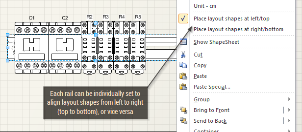
Setting Automatic Placement Orientation
Automatic Placement on Rails are set to align layout symbols from left to right or if the rail is vertical (right click, select Vertical), from top to bottom. Each rail can be individually set to align on any orientation, by simply right clicking on the rail and selecting Place Layout Shapes at Left/Top (left to right and top to bottom) or Place Layout Shapes at Right/Bottom (right to left and bottom to top) orientation.
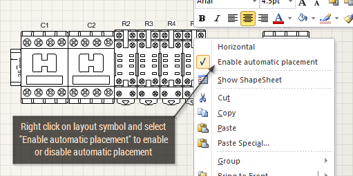
Disabling Automatic Placement
By default, all layout symbols are enabled for automatic placement on rails, but can be disabled individually or globally. To disable automatic placement on rails globally, see Automatically Place Layout Symbols on Rails. To disable a layout symbol from automatic placement individually, simply right click on any layout symbol and select "Enable automatic placement", to uncheck this option. Once unchecked, this individual layout symbol will not be automatically placed. This is useful for certain layout symbols like base plate, or relays that is placed on relay base.
Using 3D Layout Shapes
To use the Layout 3D shapes, open the stencil "Layout3D E8.vss" in the C:\Program Files\Radica\Electra\ folder. Make sure the folder is opened in your document when you generate layout.
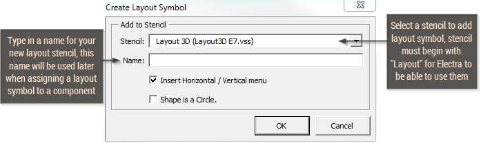
Making Your Own Layout Shapes
To make your own layout shape:
- Draw lines, arcs and graphics or import a CAD drawing and convert into Visio or import an image of the layout shape.
- Group all shapes and select them.
- Click on menu Electra | Create Layout Symbol.
- Type in a name and description for the layout symbol.
- Click OK.
An icon will be generated automatically when the layout symbol is added to a stencil. Right click on the layout symbol in the stencil and select Edit Icon to modify layout symbol icon. After creating your custom icon for your layout symbol, right click on the layout symbol in the stencil, select Master Properties, and make sure to deselect Generate Icon automatically from shape data (In Visio 2010, it's called preview).