

Document Options
Accessing Electra Options
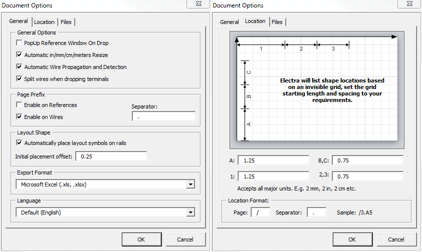
Electra comes with drawing options that can be accessed by:
- Click menu Electra | Document Options.
Popup Reference Window On Drop
To enable the Reference window to popup every time a new symbol is added to your drawings, check this option. We recommend unchecking this option for faster schematic designs. The Reference window will still be accessible by double clicking or right clicking on a symbol and selecting "Edit Reference" even when automatic popup has been disabled.
Automatic in/mm/cm/meters Resize
Electra has the ability to automatically resize symbols and circuits to fit onto pages, irrespective of the page measurement units used, be it inches, millimeters, centimeters or meters. Enable this option to let Electra automatically resize symbols and circuits to fit onto pages. When enabled, symbols and circuits that is manually resized by users will retain their sizing and will not be automatically resized by Electra.

When using metric measurement systems (mm, cm, meters) for circuit drawings, we strongly recommend that the scaling is to 1:1.5 or 1:1.25, so that symbols and circuits are displayed at optimum size.
Automatic Wire Propagation and Detection
Enable this option to let Electra automatically propagate wire name changes to all connected wires and automatically detect a wire name when it is connected to another. Disable this option to have different wire names for wires with the same potential.
Automatically manage connection dots for wires
By default, Electra has the ability to automatically manage connection dots for wires. Enable this option and Electra will automatically show dots for a connection, and remove them when there are no connections. Connection dots are also automatically hidden when you connect a wire end to another. Disable this option to manage connection dots manually.
How Page Prefix Works
Page prefix in Electra is powerful and automatic. Once enabled, Page Prefix adds a page number in front of your symbol reference or wire name and automatically keeps track and update this page number even when you rearrange your pages, all automatically.
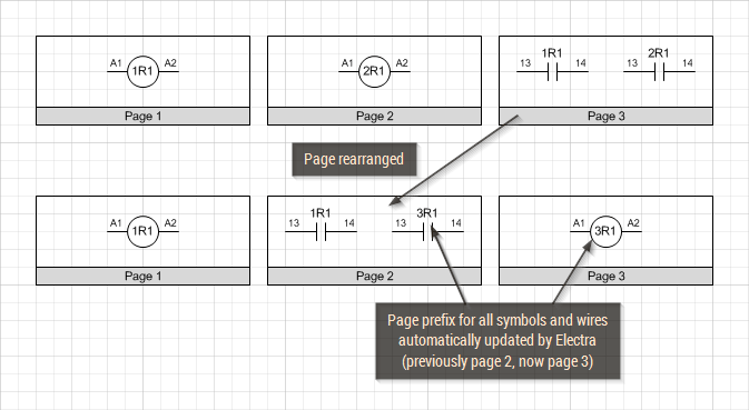
On the example above, there is a coil named 1R1 on page 1, another coil 2R1 on page 2 and 2 contacts, each of them belonging to the coil at page 1 and 2 respectively (top row of the image). When page 3 is rearranged as page 2 (bottom row of image), the coil 2R1 previously at page 2 is now automatically renamed to 3R1 on page 3. The contact 2R1 is also renamed to 3R1 since the coil it is belonging to, is now renamed to 3R1 on page 3.
Enable Page Prefix on References
Users can select to prefix a page number on all symbol references by enabling this option, and Electra will automatically insert and maintain all page prefixes. Alternatively, right click on a symbol and select "Edit Reference" to use Page Prefix.
Enable Page Prefix on Wires
Users can select to prefix a page number on all wires by enabling this option, and Electra will automatically insert and maintain all page prefixes. Alternatively, right click on a wire and select "Edit Wire" to use Page Prefix.
Page Prefix Separator for Wires
The default separator for wires is the "." character (e.g. 1.100). Page prefix separator for wires can be any character but cannot be numeric (e.g. 0-9) and can consist of more than one characters.
| Separator | Examples |
| . | 1.100, 2.100, 1.101 |
| P | 1P100, 2P100, 1P101 |
| / | 1/100, 2/100, 1/101 |
| Pg | 1Pg100, 2Pg100, 1Pg101 |
Automatically Place Layout Symbols on Rails
Electra has the ability to automatically attach and arrange layout symbols when dropped on rails. Uncheck this option to disable automatic placement of layout symbols to rails globally. Alternatively, each layout symbol can be individually disabled from automatic placement by right clicking on the symbol and unchecking "Enable Automatic Placement".
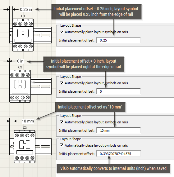
Initial Placement Offset
When layout symbols are placed on rails, Initial Placement Offset specifies the distance between the edge of the rail and the first layout symbol.
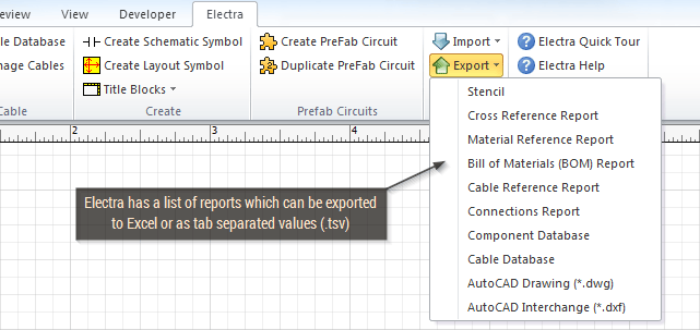
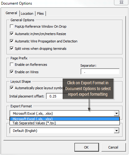
Export Format
Electra has a list of reports which can be exported to Excel or as tab separated values (.tsv). Use this option to select a format for exporting reports. Once set, Electra will export reports using the selected without the need to ask users for a format repeatedly. To select a format, click on the export format drop down and select the required export file format. If tab separated values are selected, Electra will ask for a file name during the export operation.
Location Zone Options
Electra reports shape locations (e.g. /1.A1 : Page 1 - zone A1) by dividing a drawing page into zones. To modify the location zones, click on the Location tab in Document Options and enter your preferred zone spacing.
- A: Denotes the starting spacing for vertical zones.
- B, C: Denotes the repeated spacing for vertical zones.
- 1: Denotes the starting spacing for horizontal zones.
- 2, 3: Denotes the repeated spacing for horizontal zones.

Location Format
To configure how Electra displays location information, use these options:
- Page: Denotes characters used to prefix page numbers.
- Separator: Denotes characters used to separate page numbers and location zones.
| Page | Separator | Examples |
| / | . | /3.E7, /4.F8 |
| P | . | P3.E7, P4.F8 |
| Pg | / | Pg3/E7, Pg4/F8 |
Saving Your Own Document Options
Settings under Document Options applies globally and is saved in the registry, except Location options where these settings applies to current document only and is saved inside the current drawing. If you wanted to save location options globally, you will need to create a new template using the following steps:
- Make a backup copy of the file New Electra Drawing.vst (in C:\Program Files\Radica\Electra folder).
- Open Visio and Electra by double clicking on New Electra Drawing.vst.
- Select menu Electra | Document Options and apply your custom settings.
- Do not modify the drawing, and select menu File | Save As.
- Type in your custom template name or overwrite New Electra Template.vst.
- Close Visio and restart.
The settings are now saved into the template you have chosen above. The next time you start Visio with the above template, your settings will be automatically loaded and used as the default.