

PLC and Connector Shapes
The PLC Symbol
To create a PLC module in your drawings, drag and drop the PLC symbol onto your drawings. To rotate the PLC symbol, right click on the PLC symbol and select Horizontal or Vertical. To change the label position and orientation on the PLC symbol, right click and select Change Label position or Change Label orientation.
Customizing the PLC Symbol
PLC symbols can be input, output or analog modules. To customize the PLC symbol, right click on the symbol and select Set PLC Module.
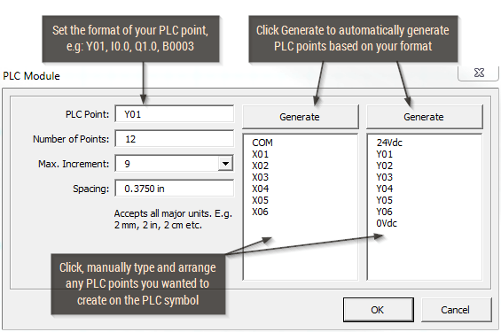
- PLC Point allows users to set the starting format for a PLC point. For example, if the PLC points starts from B00000 to B00007, type in B00000 into PLC point text box. If the PLC point starts from X00 to X07, type in X00 into the text box.
- Number of points tells Electra how many PLC points to generate. For example, if you have 16 inputs, key in a value of 16 into the number of points text box.
- Max increment tells Electra what is the maximum number when generating PLC points. For example, if you have 16 inputs, from X00 to X07, and X10 to X17, then your maximum increment is 7 as that's the maximum number that your PLC point can have. If you have 16 inputs from X00 to X0F, then your maximum increment will be F. If you have 16 inputs from X00 to X15 then your maximum number is 9.
- Spacing tells Electra what spacing to use when generating the PLC points on the PLC symbol. The Spacing text box accepts measurement units, e.g. inches, millimeters, cm and other units.
- Generate button instructs Electra to generate PLC points on the text box, based on the formats that is entered. Once generated, these PLC points can be manually edited before being generated on the PLC symbol itself. Users can also manually create PLC points by using the text box under the Generate button. Type in the desired PLC points and press the Enter key. The PLC symbol will automatically generate PLC points for each line of text in the text box. Examples of generation below:
| PLC Point | X0 | B00001 | Q0.0 |
| Number of Points | 8 | 12 | 12 |
| Max. Increment | 9 | 9 | 7 |
| Original text box content | 24Vdc Y01 Y02 | 24Vdc X0 0Vdc | 24Vdc Y01 0Vdc |
| Results after Generate | 24Vdc X0 X1 X2 X3 X4 X5 X6 X7 | 24Vdc B00001 0Vdc B00002 B00003 B00004 B00005 B00006 B00007 B00008 B00009 B00010 B00011 B00012 | 24Vdc Q0.0 0Vdc Q0.1 Q0.2 Q0.3 Q0.4 Q0.5 Q0.6 Q0.7 Q1.0 Q1.1 Q1.2 Q1.3 |
Creating a Single PLC using Multiple Symbols
Users can use the PLC symbol to create separate input and output modules and they will be displayed as separate shapes on your drawing. If you edit their reference (e.g both input and output module are labelled "PLC1") then Electra understands that both symbols represent only a single PLC module. Therefore, only a single PLC module appears on Generate Layout or on the Bills of Materials, despite having 2 separate PLC module shape on your drawings.
The Connector Symbol
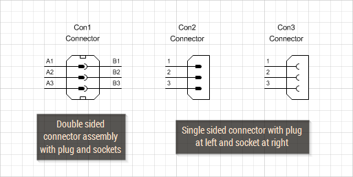
To create a connector assembly that includes both plug and socket in your drawings, drag and drop the double sided Connector symbol onto your drawings. To create a connector with plug or socket only, drag and drop the single sided Connector symbol onto your drawing. When using the single sided Connector symbols, right click on the Connector and select "Show Male Plug" or "Show Female Socket" to display male plugs or female sockets on the connector.
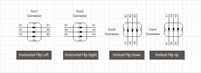
- To rotate a connector, right click and select Horizontal or Vertical.
- To switch the position of the labels on a connector, right click and select Flip Right or Flip Left or Flip Up or Flip Down.
Customizing the Connector Symbol
To customize the Connector symbol:
- Right click on the Connector symbol and select Set Connector.
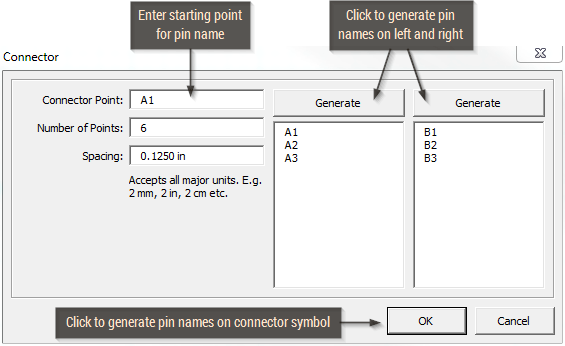
The Connector symbol operates similarly like the PLC symbol, so for more information, please refer to Customizing the PLC Module.