

Symbols and Components
One Intelligent Symbol
On some occasions, users may want to create drawings that display symbols horizontally. At other times, users may want to create vertical ones. Electra makes it easy to do both, with one single symbol. Symbols in Electra are intelligent, and can be rotated vertically or horizontally with a simple right click. Rotated symbols automatically have their text and descriptions moved to the correct positions. Certain symbols are even smarter, for example, the motor symbol will allow users to place a 3 terminal or a 6 terminal motor with just a single right click. Drop a symbol onto a drawing and right click to exlpore for more options.

Symbols in Electra are also unit agnostic. This means that you can create a single symbol and use it on multiple page units including inches, millimeters, centimeters and meters, where Electra will automatically resize your symbols so that they fit nicely on whatever units you have chosen.

When using metric measurement systems (mm, cm, meters) for circuit drawings, we strongly recommend that the scaling is to 1:1.5 or 1:1.25, so that symbols and circuits are displayed at optimum size.
Duplicating Symbols
One of the most used function is to place or duplicate a symbol. There are 2 ways to duplicate a symbol:
- Selecting a shape and then using copy and paste.
- Selecting a shape, press CTRL key, drag and drop, then release CTRL key.
Intelligent Automatic Numbering
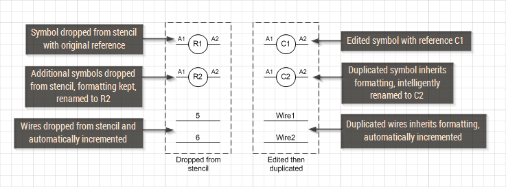
All symbols will be automatically and intelligently named when placed or duplicated on a drawing. For symbols dropped from a stencil, Electra will follow the naming format during symbol creation. For example, when you create a symbol and called it C1, then Electra will name it C1, C2, C3, etc when you drop them onto your drawings.
For duplicated symbols, Electra will follow the existing format on the symbol. For example, you dropped a symbol called C1 onto a drawing, and then renamed it Control1. When you duplicate Control1, Electra will name subsequent symbols Control2, Control3, etc, all automatically.
Assigning Pin Names
Electra automatically allocates the next available pin set when symbols share the same references. Users can right click on a symbol and select Set Pin Names to manually allocate another pin set or to show/hide pin names. Alternatively, you can click on Home | Layers | Layer Properties, and then modify the Pin layer to show or hide pin names for the entire page.
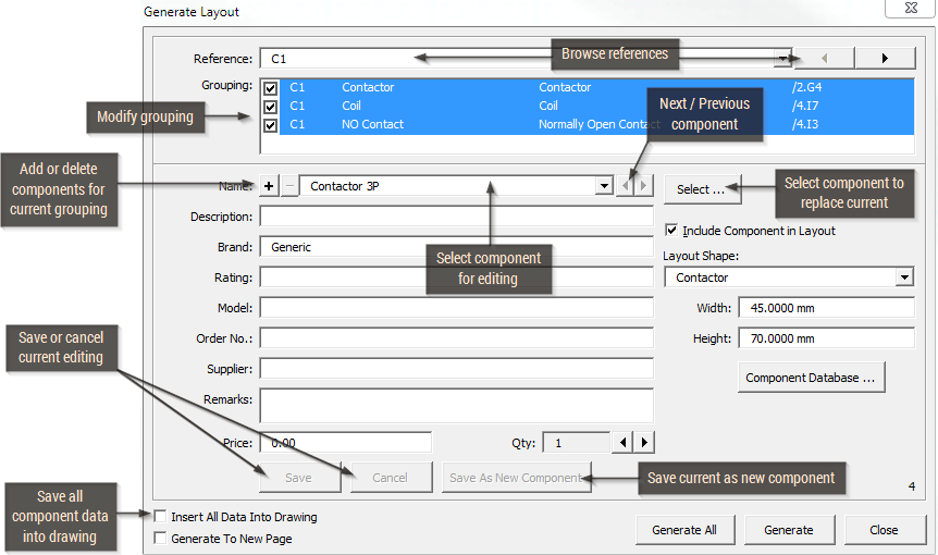
Assigning and Managing Components
Users can assign and manage components using the menu Electra | Manage Components. All symbols in Electra are organized by references and then divided into groups. Each group can then be assigned to one or more real world component. These assignments will then be used in generating layout and reports.
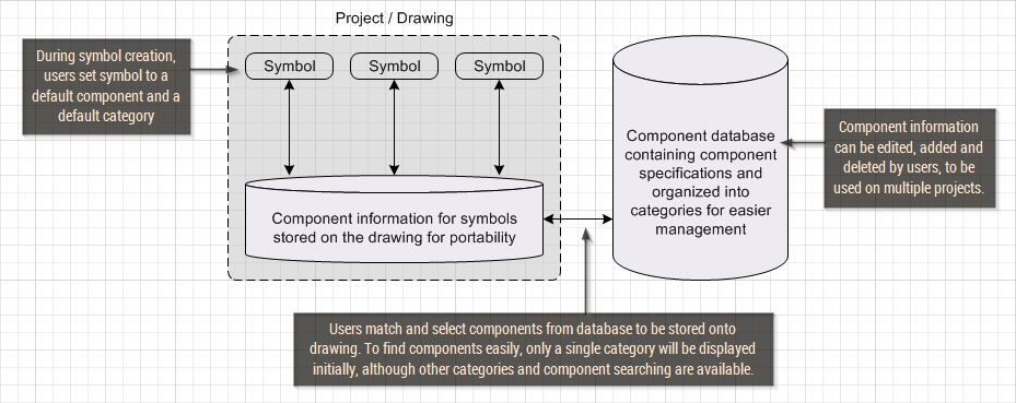
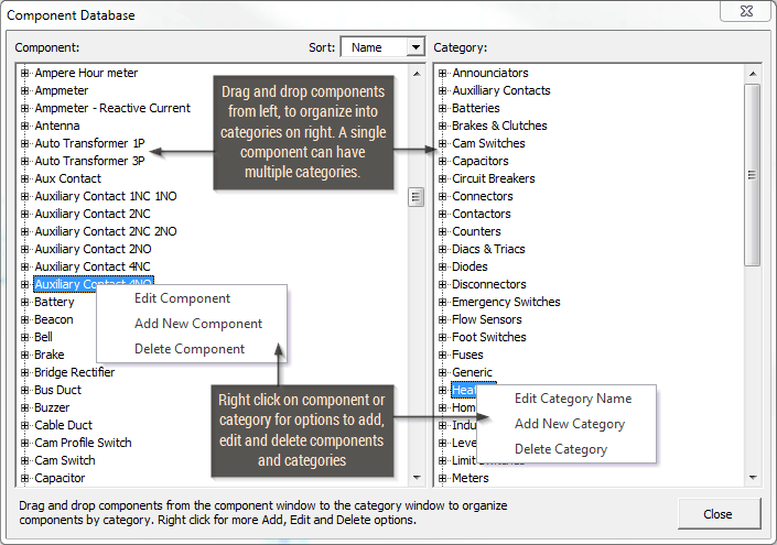
The Component Database
The Component database stores all component specifications so that they can be used and re-used on multiple projects and drawings. Once a component is selected, it's specifications is then transfered and stored on the drawing itself for portability. Components stored on the database are divided into categories and a single component can appear in more than one category.
Users can click on menu Electra | Component Database, to add, edit or delete components from the database. In addition, the entire database can be exported for editing, and imported back into Electra.
Making your own Symbols
To make your own symbols:
- Draw graphics and text.
- Group shapes together.
- Add connection points.
- Click on menu Electra | Create Schematic Symbol, fill in information and click OK.
During symbol creation, Electra will ask users for a category. This category will then be used during component management where only components with the same category is initially presented to the user. For example, if a symbol is assigned to the "Motor" category, during component management, only motors will be initially presented. Users can then select a component from the same category or select another one from a different category. Categories are used to facilitate easier component management and selection.
The AutoLocation shape
The AutoLocation symbol displays the location of your references automatically in real time, all without user interference. Locations will update automatically when you move symbols, even across multiple pages. Right click on an AutoLocation shape to jump to monitored references. Multiple AutoLocation symbols can be used to monitor the same reference on multiple pages.